Thermite Welding Rail Joints: Why Grinding Is Half of the Job
- Share
- publisher
- RailwayCare
- Issue Time
- Sep 15,2026
Summary
Thermite welding rail joints and grinding are complements: what the process leaves behind, the 2025 shift to flash-butt welding, and how joints are accepted.
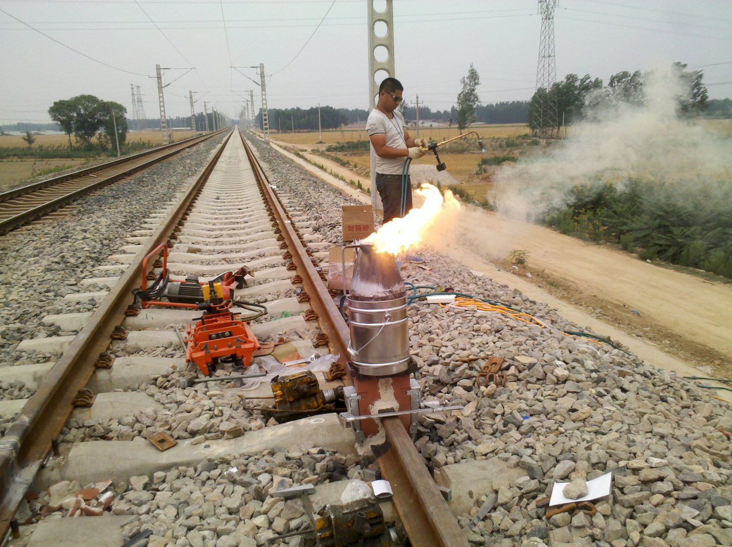
A thermite weld is made in about 60 seconds of violent chemistry and a few minutes of solidification - and then the joint is only half finished. What the process leaves behind is a raised collar, a heat-affected zone with a different hardness from the rail, and a running surface that no wheel should ever touch until it has been cut and ground back into the parent profile.
That is the relationship between two technologies that are usually discussed as rivals: thermite welding rail joints and rail grinding are complements. One joins the steel; the other makes the joint fit to carry traffic. This article explains what thermite welding actually does to the steel, what it leaves for grinding to fix, how the 2025 Chinese policy on new-build lines changes where the process is used - and why the grinding demand does not go away when the welding method changes.
We supply the grinding wheels used for weld finishing, on hand machines and on grinding trains, so this is written from the consumable side of the joint.
What Thermite Welding Actually Does to a Rail
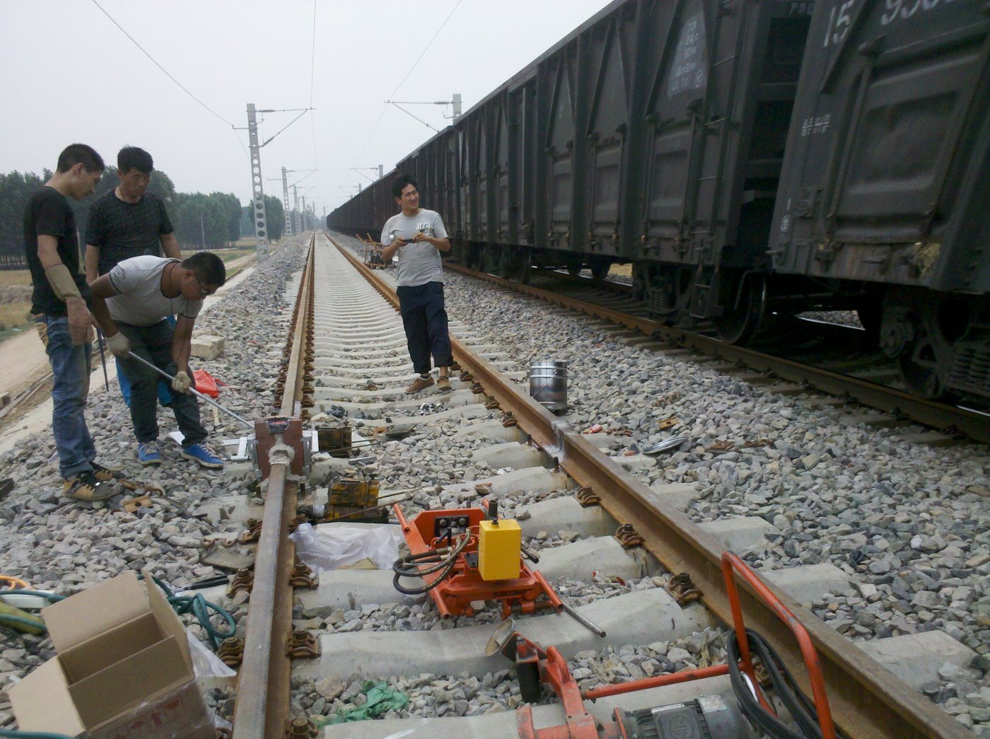
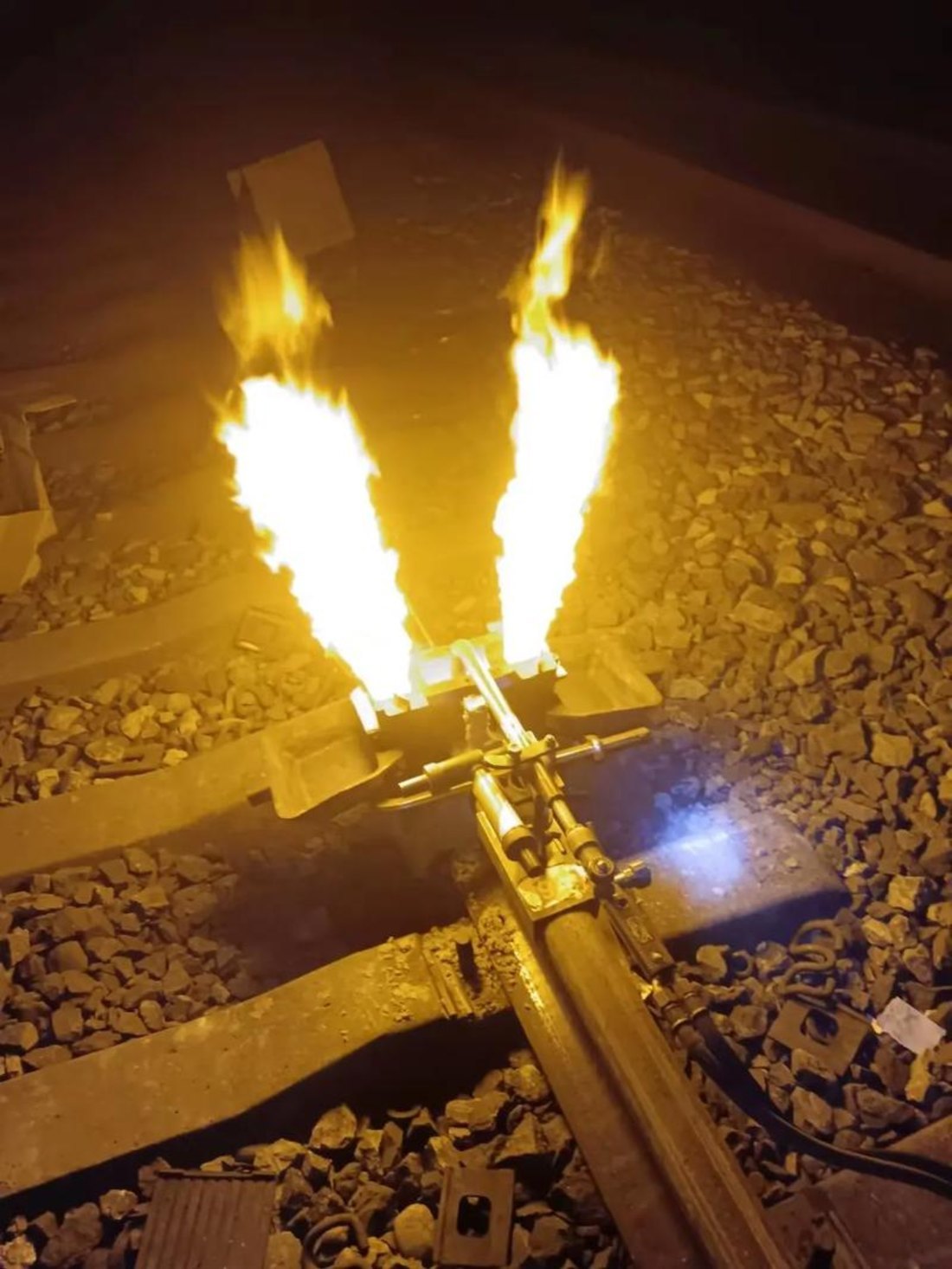
Thermite (aluminothermic) welding is a casting process disguised as a weld. Aluminium powder reduces iron oxide, and the reaction - roughly 3FeO + 2Al → Al2O3 + 3Fe, plus around 880 kJ - takes the products above 2,500 °C within a minute. The molten steel fills a mould clamped around the rail gap and fuses with the preheated rail ends; the slag floats out and is trapped in the crucible.
The process parameters that decide whether the joint will survive traffic are unforgiving, and they are broadly consistent across suppliers and standards:
| Step | Typical parameter | Why it matters |
|---|---|---|
| Rail gap | 25-30 mm | Sets the volume of steel needed to fill the cavity without cold laps or shrinkage |
| Preheating | Rail ends to roughly 900-1,000 °C | Removes moisture and prevents the molten steel cooling too fast |
| Reaction | >2,500 °C, complete in under a minute | Determines slag separation and steel cleanliness |
| Cooling in the mould | 10-15 minutes, typically demoulded below ~300 °C | Controls cooling stresses in the weld and the heat-affected zone |
| Hot shearing | Shear the collar at 700-850 °C with a hydraulic trimmer (>120 kN) | Removes most excess metal while it is still ductile; industry practice reports roughly 60% less subsequent grinding |
| Profile grinding | To the rail profile, to the operator's geometry tolerance | Restores the running surface; see our weld-to-grind workflow |
| Inspection | Ultrasonic testing or magnetic particle inspection | Verifies the joint before it is accepted for traffic |
Two standards matter commercially. EN 14730 is the benchmark specification for aluminothermic welding procedures in Europe and in markets that certify to European practice; in China, Q/CR 1-2014 (rail grinding train wheel ordering conditions) and the operator's track maintenance rules govern the finished joint and the grinding that produces it.
What a Thermite Welding Rail Joint Leaves Behind
Once the mould is off and the collar is sheared, five features remain that only grinding (and inspection) can deal with:
- A weld hump or a low spot. If the collar is not fully removed, the joint protrudes; if the finished weld settles in service, it dips. Both are geometry faults, and both hit every wheel that passes. A low spot is the more damaging of the two - it produces a dynamic impact that scales with speed.
- A heat-affected zone with a different microstructure. The weld steel is cast, the parent rail is rolled - and on head-hardened grades the parent can run at 350-400 HB. The gradient across the joint is where fatigue damage tends to start.
- A casting skin. The first fractions of a millimetre at the running surface can carry casting defects, porosity and slag inclusions. Grinding removes that layer and exposes sound metal for inspection.
- Surface roughness that no specification accepts. Operators set Ra ≤10 μm after grinding (TB 10413-2018 and equivalent rules); a sheared weld is far coarser than that.
- A profile discontinuity. The joint has to carry the same contact geometry as the parent rail. If the profile through the weld differs, the contact band breaks at the joint - which is exactly what the Chinese standard on turnout connections warns against when it requires the rail section and profile to match across the connection.
This is why China's rail administration classifies grinding, straightening and welding repair (打磨、矫直、焊补) as the three accepted means of reconditioning turnout rail (运基线路〔2004〕354号, clause 7.1.3). Grinding is not cosmetic work at a joint; it is one of the three recognised repair processes.
The 2025 Shift in Thermite Welding Rail Policy
In 2025 the picture changed for new construction. Following a fracture of a curved-leg weld in turnout 228 at Gasi Lake station on the Golmud-Korla line, China Railway's electrical and signalling department issued a notice (工电线路电〔2025〕5号) whose practical effect is now a professional management requirement: on newly built and reconstructed railways, flash-butt welding and gas-pressure welding should be used in place of thermite welding.
The stated reasons are worth reading carefully, because they describe the failure modes rather than the process:
- thermite weld metal has lower strength than the parent rail, which is a design inheritance of a casting process;
- the joints are prone to surface depression (low spots), which increases dynamic loading;
- thermite welds require far more frequent non-destructive testing than flash-butt or gas-pressure welds, which adds inspection workload and operating cost over the asset's life.
The same body of guidance preserves the boundary: locking welds inside a turnout and between the turnout ends and the running line may still use thermite welding (TB 10082—2017, clause 8.0.6), and field welding in general is directed towards flash-butt where it is practical.
The engineering consequence for anyone who owns grinding assets is straightforward and easy to miss: a change of welding method changes the amount of grinding, not the need for it. A flash-butt weld arrives at the track with a trimmed, forged, ductile joint and needs relatively light finishing. A thermite weld arrives as a casting that must be sheared hot and then ground. On a network that switches new-build welding to flash-butt while continuing to use thermite for locking welds, the total grinding load shifts but does not shrink - and the joints that remain thermite-welded are, if anything, the ones with the least forgiving geometry.
Where Thermite Welding Rail Practice Still Wins
The 2025 guidance is a policy on new lines, not a verdict on the process. Thermite welding keeps advantages that no other field method matches:
- No external power and a small equipment footprint. Kits are portable and self-contained, which is why the process dominates in remote locations, tunnels and confined urban sites.
- Speed per joint in constrained conditions. Metro and light-rail practice typically completes a joint in 45-90 minutes, which fits inside short night possessions.
- Versatility. Thermite kits can join different rail sections, rails with different wear depths, and can be built into insulated joints - cases where flash-butt machines are impractical.
- Locking and closure welds. As the Chinese guidance confirms, closure welding at turnouts and the final joints of a string remain thermite territory.
For high-speed and heavy-haul applications, the process is used with alloyed charges, tightly controlled preheating and mandatory post-weld grinding to tight geometry tolerances. Heavy-haul joints on 25-40 tonne axle loads are the case where the finishing operation carries the most responsibility, because the weld is where a fatigue crack has the best chance to start.
What Grinding Contributes to a Thermite Weld
Grinding does three jobs at a welded joint, and only the first one is about looks:
- Geometry. Remove the residual collar and restore the transverse profile and longitudinal straightness through the weld. The working tolerance in this class of work is a fraction of a millimetre over a one-metre straightedge - our own workflow guidance uses 0.3 mm over 1 m with a feeler gauge.
- Surface condition. Cut back the casting skin to sound metal, bring roughness inside the Ra ≤10 μm acceptance limit, and leave no continuous blue band. Burn at a weld is doubly expensive: it damages the joint you have just made and it will be recorded at inspection.
- Contact continuity. Ensure the contact (light) band runs unbroken across the joint, at the correct width and position - 25-30 mm on high-speed track and 35-40 mm on conventional and heavy-haul track. A correct profile with a misplaced band still produces impact loading.
How far the grinding pass has to run along the rail on each side of the weld - the grinding length - is a parameter in its own right, and one where most field work is under-specified. We have written separately about why grinding length is the unseen critical parameter in weld seam finishing.
How the Welding Method Changes the Grinding Job
If you are specifying consumables, this is the table that matters - the same joint requires a different grinding effort depending on how it was made:
| Welding method | What arrives at the track | Grinding load at the joint |
|---|---|---|
| Thermite (aluminothermic) | Cast joint, collar cut hot with a trimmer, casting skin intact | Highest: full profile and straightness restoration, skin removal, roughness finishing |
| Flash-butt | Forged joint, flash trimmed by machine shears while hot | Light: finishing pass to profile and roughness; geometry usually close already |
| Gas-pressure | Forged joint, similar to flash-butt but with a different heat source | Light to moderate, depending on the trimming equipment on site |
| Repair or build-up weld | Local deposit on a damaged or worn area | Variable: matching the deposit to the surrounding profile and hardness |
The consumable consequence is equally practical. Where the grinding load is high, the wheel is being asked to cut cast steel, remove the weld collar remnants and finish a hardness gradient - all without loading up, glazing or burning the parent metal. That is a harder duty than plain-line profile grinding, and it is why a general-purpose wheel from a catalogue rarely survives a full joint programme. The wheel has to combine a tough grain with a bond that releases it before it polishes the surface; the failure mode to avoid is described in our article on rail burning prevention and wheel choice.
Choosing Wheels for Weld and Joint Grinding
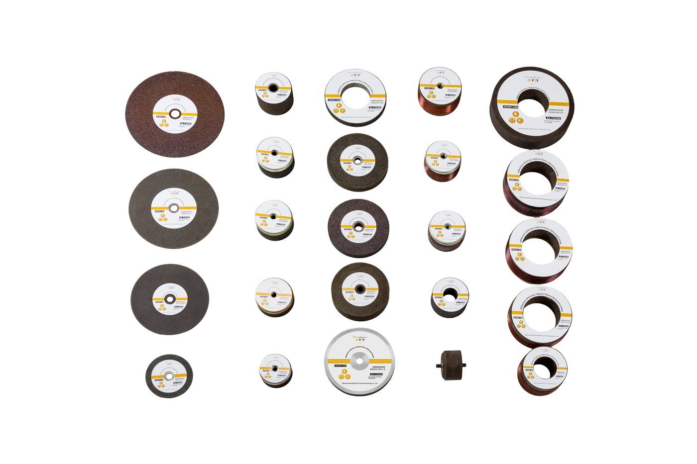
Weld finishing is mostly hand-machine work, and the wheel formats are correspondingly smaller than grinding-train wheels:
| Application | Typical wheel formats |
|---|---|
| Hand machines (Geismar / Robel compatible) | 150×70×M20, 150×65×M20, 150×75×32, 150×56×M20, 150×70×55-4×M8 |
| Smaller hand machines | 125×65×20-54×47, 125×65×20-36×18 |
| Other joint and rail work | 180×80×M20, 230×60×25, 250×32×32, 260×25×120, 254×32×25.4 |
| Grinding trains (joint work in a campaign) | 260×90×154, 260×90×153, 250×75×150, 180×105×90, 260×83×152, 350 series |
Specification points that decide performance at a joint:
- Abrasive and bond. Zirconia alumina in a resin bond with glass-fibre wrapping, 16 grit, is the default for rail work: compressive strength of 308.0 MPa and a grinding ratio of 41.0 in the Shenhua project test programme, against 124.0 MPa / 22.4 for calcined brown alumina and 103.2 MPa / 11.9 for white alumina.
- Rated speed and balance. 50 m/s rated speed, balance grade G1 ≤30 g or G3 ≤34 g, and mounting holes at the correct thread and engagement (M10 holes require ≥17 mm effective engagement on grinding-train wheels).
- Dimensional tolerance. Outside diameter ±2.0 mm, thickness ±1.5 mm, parallelism ≤0.4 mm, coaxiality ≤0.5 mm - tight enough that the wheel runs true at 3,000-6,000 rpm without introducing a pattern of its own.
Acceptance and Verification at a Welded Joint
A finished weld is accepted on four measurements plus one inspection:
| Check | Requirement |
|---|---|
| Roughness | Ra ≤10 μm after grinding (TB 10413-2018 and equivalent) |
| Straightness / geometry | Fraction of a millimetre over a 1 m straightedge with feeler gauge (0.3 mm in our workflow) |
| Burn | No continuous blue band |
| Contact band | Unbroken across the joint; 25-30 mm high-speed, 35-40 mm conventional and heavy-haul |
| Internal soundness | Ultrasonic testing or magnetic particle inspection, per the welding standard in force (EN 14730 practice or operator rules) |
Our own wheel evidence, from the programmes our wheels run on: samples passed rotary safety testing at 6,354 r/min without fracture; in a trial acceptance on Chengdu Metro small-radius curves, Molaton M20×2.5 stones scored 90/100 to TB 10413-2018 with the restored heads passing roughness and light-band checks; and in a Loram-machine trial at Jiangmen, roughness across all ground rails measured 1.05-9.0 μm, mostly 2-4 μm, with no blue bands. Durability at the consumable level, measured on a GMC-96X half-car comparison (48 of our wheels against 48 imported wheels, same machine), was roughly 1.5× the imported benchmark with comparable quality - and a weld programme is exactly the kind of work where that difference shows up as fewer wheel changes per possession.
Where Molaton Wheels Fit in Weld and Joint Work

Molaton rail grinding wheels are manufactured by RailwayCare (Wuhan Huatie Ruijie Rail Transit Technology Co., Ltd.) at 500,000 wheels per year, in the hand-machine, turnout and grinding-train formats used for weld finishing and joint campaigns.
- Formats for the duty. Hand-machine wheels in the 125-260 mm range with M20, 5/8" and M8 mounts, plus every grinding-train format in service.
- Zirconia alumina, 16 grit, resin bond, glass-fibre wrapped, rated 50 m/s.
- Certification for procurement. ISO 9001:2015 and ISO 45001:2018, CRCC, technical review by the China Academy of Railway Sciences (TKTJ-19-0007-ST), a report from the Zhengzhou National Abrasives Quality Inspection Centre, JB/T 11431-2020, EN 12413 and EAC/GOST 33174-2014 for 1,520 mm gauge markets.
- Verified life. ≥100 pass-km in the G1 test outline, plus the field results above.
For adjacent reading, our guides to rail welding and grinding as one workflow, rail head grinding and corrugation and joint-related defects cover the rest of the joint's life.
Is thermite welding still allowed on railways?
Yes - the process remains in wide use, particularly for metro and light-rail work, confined and remote sites, repairs, different rail sections and insulated joints. What changed in China in 2025 is the preference for new construction: guidance following a weld fracture (工电线路电〔2025〕5号) directs that flash-butt and gas-pressure welding be used in place of thermite welding on newly built and reconstructed railways, while locking welds at turnouts may still be thermite (TB 10082—2017, clause 8.0.6).
Why does a thermite weld need grinding after the collar is cut?
Because shearing removes the bulk of the excess metal but leaves the geometry and the surface unfinished: a residual hump or low spot, a casting skin that can contain porosity and inclusions, roughness far above the Ra ≤10 μm acceptance limit, and a profile that may not match the parent rail. Grinding restores the profile, the straightness, the roughness and the contact band across the joint.
Does hot shearing remove the need for grinding?
It significantly reduces it. Trimming the collar while the weld is still between roughly 700 °C and 850 °C, with a hydraulic trimmer applying more than 120 kN, is reported to cut subsequent grinding time by around 60 per cent and avoids subjecting the heat-affected zone to unnecessary grinding stress. The finishing pass is still required, because geometry and roughness tolerances are tighter than any trimmer can hold.
What does grinding have to achieve at a welded joint?
Four measurable things: the transverse profile and longitudinal straightness restored to the operator's tolerance (a fraction of a millimetre over a one-metre straightedge), surface roughness within Ra ≤10 μm, no continuous blue band, and a light band that runs unbroken across the joint at the correct width - 25-30 mm on high speed, 35-40 mm on conventional and heavy-haul track. Internal soundness is then verified by ultrasonic or magnetic particle inspection.
Which grinding wheel should be used for weld finishing?
For hand-machine work, a 150 mm format wheel (for example 150×70×M20 or 150×65×M20) in zirconia alumina, 16 grit, resin bond with glass-fibre wrapping and a 50 m/s rating, balanced to G1 ≤30 g. The duty is severer than plain-line grinding because the wheel has to cut cast weld metal and a hardness gradient without glazing or burning the parent rail, so a tough grain with a free-cutting bond matters more than a low price per wheel.
Get Weld-Finishing Wheels That Match the Joint You Have to Make
Tell us the welding method, rail section and grade, the machine you finish with, and the geometry and roughness tolerances you have to hold - and we will come back with the wheel specification, the expected number of joints per wheel with its test basis, and a commercial frame you can compare against any other supplier.
- WhatsApp: +86 15072332788
- Email: simon.wang@railwaycare.com
RailwayCare (Wuhan Huatie Ruijie Rail Transit Technology Co., Ltd.) – your professional partner in rail grinding, with Molaton grinding wheels field-proven on high-speed, heavy-haul and metro lines since 2004.
RailwayCare (Wuhan Huatie Ruijie Rail Transit Technology Co., Ltd.) – your professional partner in rail grinding, with Molaton grinding wheels field-proven on high-speed, heavy-haul and metro lines since 2004.