Railroad Diamond Crossing: Structure, Wear and Grinding Maintenance
- Share
- Issue Time
- Oct 15,2026
Summary
Railroad diamond crossing guide: structure, why a diamond wears faster than plain line, inspection, frog and flangeway grinding, and the wear limits that force replacement.
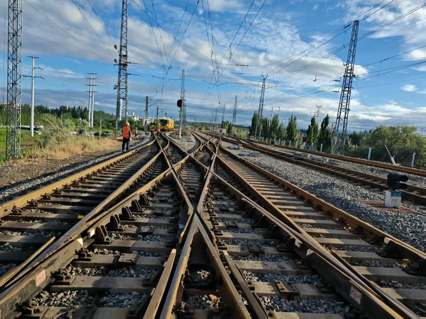
A railroad diamond is the one piece of trackwork where two routes at grade share a single structure, and where every wheel that passes either route lands on the same castings. It is an assembly of four separate crossings packed into the length of a road vehicle, crossed by two traffic streams, and asked to survive impact loads that no other part of the track sees. That is why a diamond costs more to maintain per metre than any other part of the permanent way — and why the maintenance decision that matters most is not whether to grind it, but whether the geometry you put back is the geometry the two routes actually need.
This guide covers what a railroad diamond is and how it is put together, why it wears faster than plain line, what to inspect and how often, how to grind the frogs, wing rails and check rails without destroying the flangeway, the wear limits that force a speed restriction or a replacement, and what a finished crossing has to meet before the line reopens.
In one sentence: a diamond crossing is two acute-angle crossings and two obtuse-angle crossings built as one assembly, and grinding it correctly means restoring metal flow and profile on four separate corners while holding the guard check gauge and the flangeway that let the wheels pass through.
What a Railroad Diamond Actually Is
The term covers two different things, and the first job is to know which one you are dealing with.
The structure. A diamond is a crossing at an obtuse angle — the arrangement that lets two tracks cross each other at grade rather than merge. The textbook decomposition is that an obtuse angle crossing consists essentially of two acute angle crossings and two obtuse angle crossings, brought together in one assembly. A single diamond handles one pair of intersecting lines; clusters of diamonds handle three or more routes meeting in the same area, which is common in station throats, yards and terminals.
The component. In North American and British practice "diamond" is also used loosely for the crossings themselves, and in a four-corner diamond you will hear the acute corners called frogs and the obtuse corners called, simply, the obtuse crossings. The distinction matters because the two types fail differently and are ground differently.
The most common confusion is with a turnout. A turnout takes one route and splits it into two, with a switch at the toe and a frog where the diverging route crosses. A diamond takes two routes that already exist and lets them cross, with no switching function at all. There is no point machine, no switch rail and no facing move to set — the whole assembly is fixed trackwork, and every wheel goes where its flangeway sends it. Where the two meet is at the fouling point, where a crossovers and a diamond share the same restricted space, and that is the reason both appear in the same scope of work in a grinding or inspection contract. How those restricted zones constrain machine access is set out in our guide to large machine turnout grinding and where grinding has to stop.
A right-angle version exists — the square crossing — but it is deliberately avoided on running lines. Two tracks crossing at 90° put the wheel through the longest possible unsupported gap at the worst possible angle, and the wear rate makes it uneconomic outside low-speed yards.
Why a Railroad Diamond Wears Faster Than Plain Line
Four mechanisms act at once on a diamond, and none of them is present on plain line.
The flangeway is a gap the wheel has to cross. At every crossing in the assembly, the wheel stops being supported by the rail it is running on and momentarily transfers onto the nose of the crossing beyond a gap in the running surface. On plain line there is no such gap. The wheel does not roll over a crossing; it lands on it. The published inspection guidance for these structures puts the dynamic force in a traditional diamond at up to three times the static loading — and the sharper the crossing angle, the worse it gets, because a sharper angle means a longer unsupported span at a flatter approach.
Two routes share one casting. A turnout frog carries the traffic of one route that diverges. A diamond frog carries the traffic of both routes crossing it. Tonnage accumulates at twice the rate, and it arrives from two directions, so the wear pattern is not a single polished band but a set of intersecting ones.
Four corners wear unequally. In a four-corner diamond the acute and obtuse corners do not see the same load or the same number of wheel passes, so they wear at different rates. This is why the maintenance regime for these structures includes transferring reversible crossing inserts between corners to equalise wear — a scheduled rotation that exists purely because the wear is asymmetric by design.
The ballast and subgrade underneath are worked harder. The impact loading that damages the castings also pulverises the ballast beneath them, and a pulverised, water-trapping subgrade feeds back into the problem by removing the support that would have spread the load. That is why the guidance for these structures is explicit that the sub-grade under a crossing must be well drained, and that ties under a crossing must be sound and firmly tamped for 16 inches either side of both rails on both routes — not just on one.
The consequence for maintenance planning is that a diamond is a shared critical asset. Any work on it interrupts both routes at once, and any speed restriction on it slows both routes. That changes the economics of the whole decision: it is worth grinding earlier and more precisely than plain line, because the cost of getting it wrong is paid twice.
The Components That Take the Load
A crossing assembly is built from a specific set of parts, and knowing which one you are looking at determines what the grinding job actually is.
| Component | Function | What goes wrong |
|---|---|---|
| Vee piece (nose) | The pointed running surface where the two running edges converge | Metal flow, chipping, nose wear; needs alloy steel and adequate nose thickness |
| Point rail | The rail section carrying the running edge into the nose | Vertical wear, shelling at the nose |
| Splice rail | The mating section bolt-fitted alongside the point rail to form the vee | Joint gap creep, edge flow at the mating face |
| Wing rails | Guide the wheel across the flangeway onto the nose | Flangeway edge flow, wear on the guiding face |
| Check rails | Hold the wheel away from the nose on the opposing route | Side wear on the check face, gauge loss |
| Heel blocks | Anchor the assembly at the throat, nose and heel | Loosening, fretting under impact |
| Reversible inserts | Sacrificial corners that can be rotated to equalise wear | Uneven wear between the four corners |
The design requirements are worth stating because they explain why the assembly is expensive to make: the crossing assembly must be rigid enough to withstand severe vibration, and the wing rails and the nose — the two parts that meet every wheel — are specified in special alloy steel precisely because ordinary rail steel will not survive the duty.
Two grades of material dominate in practice. Cast manganese steel crossings are the traditional heavy-duty answer and are valued for their ability to work-harden under impact while staying tough enough not to crack; the trade-off is that they are repaired by welding and re-profiled by grinding rather than by machining. Rail-bound crossings built from machined, mitred rail sections bolted together are cheaper to make but, by the judgement of the people who maintain them, more prone to failure in service. For maintenance planning this matters, because the two types have different repairable limits: a manganese casting can absorb repeated weld build-up as long as the heat input is controlled, whereas a bolted rail assembly tends to reach its limit at the joints.
Fixed and Movable Point Diamonds
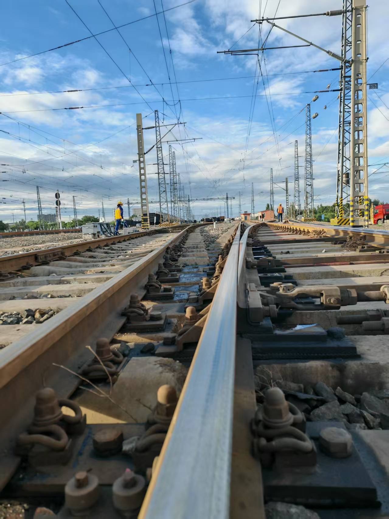
The single biggest structural decision in a diamond is whether the crossing is fixed or movable, because it changes both the impact loading and the maintenance regime.
Fixed crossings are the default. The flangeway is a permanent gap, the wheel has to bridge it, and the structure absorbs the impact. The published maintenance regime for these assemblies is a good summary of what fixed operation demands: metal flow on the frogs must be ground off to maintain gauge and to prevent chipping; repairs where necessary are made by welding to approved methods; reversible inserts are rotated between corners; and the crossing must be fully bolted, with spring washers or hardened steel flat washers to the manufacturer's plan and kept tightened to the prescribed torque.
Movable point crossings close the gap. Instead of a permanent flangeway, the crossing contains components that move to present a continuous running surface for whichever route is set. Two variants exist. The spring or movable crossing uses a moving element driven by the wheel flange itself or by an actuator. The more advanced approach is a set of moveable flangeway gap fillers — load-bearing pistons that are positioned before a movement is authorised across the crossing — producing a continuously level running surface across the diamond. The mechanism is actuated hydraulically or electrically, and the reported advantage is largest at large intersection angles, which is exactly where the fixed-diamond problem is most severe.
Movable crossings shift the maintenance burden from wear to mechanism. They must be lubricated with an approved lubricant, their actuation must be proven before a route is set, and their position must be monitored. What they buy is the elimination of the impact load, which in turn protects the frogs and the subgrade under them. Where the tonnage and the crossing angle justify the capital cost, they are the only structural answer that removes the root cause rather than managing it.
What to Inspect and How Often
Crossing inspection is a three-tier regime, and the tiers exist because the failure modes appear at different rates.
Every passage — visual. The assembly is looked at on every train that goes over it. This is not a formality: the damage mode for these structures includes chunks up to 8 inches long and 2 inches deep breaking out of a casting at the point or the corner, and a defect of that size needs to be seen before the next wheel arrives, not at the next scheduled inspection.
Monthly — on foot, with measurement. At least monthly the crossing is walked, the gauge and the flangeways measured against the plan of the crossing and the overall condition observed. Two specific gauges are checked here, and both are frequently misunderstood:
| Check | Value | What it controls |
|---|---|---|
| Guard check gauge | 4 ft 6-5/8 in (54-5/8 in / 1,387.5 mm) | Distance from the gauge line of the frog to the guarding face of the guard rail |
| Guard face gauge | 4 ft 4-3/4 in (52-3/4 in / 1,339.4 mm) | Distance from the face of the frog wing to the guarding face of the guard rail |
| Flangeway | 1-7/8 in (47.6 mm) | The gap the wheel crosses |
Both gauges are set by the plan and both are to be maintained as prescribed. Where flangeway and guard gauge drift, the wheel either strikes the nose or is guided into it, and the resulting damage is not gradual.
Annually — detailed component inspection. Once a year, and more often if the responsible engineer directs it, every component of the crossing is examined closely. This is where casting condition, insert wear, bolt condition and subgrade evidence get a proper assessment rather than a passing look.
To these three tiers the approach-track checks belong, and they are not optional extras — they are what stops the diamond being destroyed by the track next to it. The line, surface and gauge of the track approaching the crossing must be accurately maintained, and sufficient rail anchors must be applied on all approach tracks to prevent rail creep and skewing of the crossing. A diamond that is skewed out of square by rail creep loses its geometry whatever condition its castings are in, and no amount of grinding will put it back. The measurement logic that applies to the approach track is the same gauge logic described in our guide to rail gauge and how track geometry is measured correctly, and the same principle behind wear measurement generally — establish the section you are actually working with before deciding what to remove — is set out in our guide to measuring rail wear and when to grind or replace.
Grinding the Frogs: Refacing a Worn Crossing
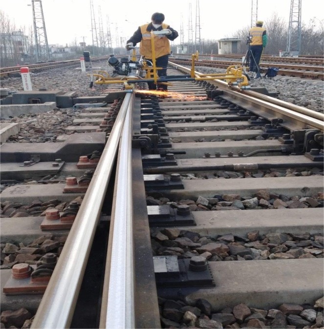
Grinding is the primary maintenance action on a diamond, and the industry has a specific name for the corrective version of it: refacing the frogs — the process of restoring the proper profile by a combination of welding and grinding. The routine version, without welding, is the removal of metal flow.
Metal flow comes first, and it is not cosmetic. The standing requirement is that metal flow on the frogs be kept ground off — the purpose is stated as maintaining proper gauge and preventing chipping. This is the key insight about frog grinding: you are not polishing the running surface, you are protecting the gauge. As wheels work the running edge, steel is displaced plastically toward the flangeway side, and the resulting lip narrows the flangeway and shifts the effective gauge. Leave it and the flangeway closes; remove too much and you open the check gauge beyond its limit. Both errors put the wheel in the wrong place relative to the nose.
Where to start depends on measurement, not on appearance. In the Chinese maintenance practice used by operating bureaux, the frog is assessed by measuring the lowering value of the point rail at the 20 mm and 50 mm cross-sections with a dedicated lowering-value gauge, after marking those cross-sections with a section calliper. The rule that follows from the measurement is the one worth carrying across to any crossing:
- If the point rail is higher than the specified lowering value, grind the point rail.
- If the point rail is lower than the specified value, grind the wing rail.
That single rule prevents the most common and most expensive error in frog grinding — taking metal off the wrong component and deepening the mismatch you were trying to correct. On a diamond, where four corners interact, getting this backwards on one corner changes the wheel path across the whole assembly.
Respect the shape of the point rail. Where the point rail top surface carries more than one slope — the Chinese practice describes three faces separated by two break points at the 20 mm and 50 mm cross-sections — each face is ground to its own slope, and the 1 m straightedge is used to control the flatness of all three. Grinding a single flat across a three-face point rail does not restore the profile; it creates a new one that the wheels did not ask for.
Work the full set of defects, not just the visible wear. The stated purpose of frog grinding is to remove fat edge, bruising and spalling, shelling, a poor running band and uneven wear. On alloy steel crossings there is one more task the routine must include: chamfer grinding of the joint between the spliced sections, done specifically to prevent chunks breaking out of the joint. This is the preventive step that keeps an otherwise sound assembly from developing the kind of spall that forces a weld repair.
Finish by polishing, and then clean up. The last stage is to remove the grinding marks and burrs from the working face, the top face and the non-working face using a flexible abrasive disc, and then to sweep the grinding debris out of the flangeways and off the assembly. Debris left in a flangeway is a hard object sitting exactly where the wheel flange has to pass.
Grinding Wing Rails and Check Rails Without Losing the Flangeway
The wing rails and check rails are where the flangeway is defined, so they are where grinding is most likely to do harm.
Wing rail top-face wear. The wing rail is ground from outside inward, using the lowest point of the vertical wear as the datum, to bring the high part down to the general running surface and keep the wing rail top flat and continuous with the rest of the assembly. The grinder travel has to be even and steady, and the entry and exit of each pass need a controlled transfer of pressure — an abrupt start or stop leaves a step, and a step on a wing rail is an impact point for every wheel.
Wing rail edge chamfer. Once the fat edge on the wing rail has been removed, the working edge is given a chamfer over the length corresponding to the 20–50 mm point-rail section. The Chinese maintenance specification sets it at 4–6 mm wide and 0.5–1.5 mm deep, and requires the running band on that section to be checked afterwards to confirm the intended effect was achieved. The chamfer is not decoration: it removes the sharp arris that would otherwise chip, and it shapes where the wheel contacts.
Grinder sweep. When finishing these faces by hand-guided machine, the lateral sweep of the grinder is held to no more than 0.5 m — a wide uncontrolled sweep cannot hold a chamfer or a break point.
Check rails. The check rail's job is to hold the wheel away from the nose on the opposing route, so its guiding face is the surface that has to be right, and the guard face gauge it establishes is a hard number, not a range you can grind into. Grinding a check rail for appearance, or dressing its head without measuring the resulting guard face gauge, is how a crossing starts striking wheels on the nose.
The flangeway itself is a dimension. Every pass on a wing rail or a check rail changes the flangeway it borders. The correct sequence is measurement before grinding, grinding to restore the running surface and the edge, and measurement after to confirm that gauge, flangeway, guard check gauge and guard face gauge are all still inside the plan. Where a small machine cannot reach a face, the answer is to change machine or change access, not to accept an unfinished face — the restriction zones that make this difficult are the same ones that apply in turnout work, and our guide to choosing a rail grinder for switch and turnout work sets out how clearance drives the machine choice.
Wear Limits, Speed Restrictions and Replacement Triggers
Not every worn crossing should be ground, and knowing when to stop grinding is as important as knowing how.
The published wear limit. Where the tread portion of a casting is worn more than 3/8 inch (about 9.5 mm) below its original contour — assessed below the level of the corners where diamond crossing corner pads have been removed — a speed restriction applies and operating speed over that crossing may not exceed 10 mph. This is a useful line in the sand for planning: it defines the point at which profile grinding can no longer be claimed to have restored the crossing, because there is no longer enough metal for the profile to sit in.
The repair limit. External damage — wear or impact — can be remedied by welding and grinding to restore the profile, subject to approved methods. Internal damage, which is metal fatigue accumulating with load cycles, cannot be seen and is not detectable by visual inspection; it is evaluated by non-destructive testing, and in practice it is the finding that determines whether the crossing is replaced rather than repaired. The published observation is blunt about the consequence: replacement generally occurs well before any of the frogs has reached its repairable wear limit, because the internal condition governs.
Typical service life. For a heavy-duty crossing under mixed traffic, a working figure from maintenance experience is a lifespan of around five years or less for cast manganese frog inserts, and shorter where welding repairs or surfacing and drainage are neglected. Tonnage, speed and crossing angle are the governing variables, and the angle is the one you cannot change after installation.
Cost of getting it wrong. The capital and disruption cost of replacing a diamond is large enough to have its own literature. A major reconstruction in the United States was priced at US$115 million, and other high-profile diamond replacements have been documented specifically to show the extent of the coordination required — the work is not a possession exercise on one line but a full blockade affecting every route through the junction.
The practical planning conclusion is that a diamond should be ground on a preventive cycle derived from tonnage, with the grinding depth and the profile outcome recorded, so that the decision to replace is taken on measured loss of section and NDT findings rather than on the appearance of the castings. What a preventive cycle looks like when it is applied to rail generally, and how grinding cost per kilometre is calculated, is set out in our guide to what operators actually pay per kilometre of rail grinding.
Machines and Grinding Wheels for Crossing Work
Crossing work splits the machine fleet in two, and the split is driven by access rather than by grinding capability.
Production grinding trains will grind crossings where the geometry allows the head to reach, and are the economical answer on long campaigns that include diamonds in the scope. Their limitation is reach: the restricted zones inside a crossing assembly, and the fouling points where two routes overlap, stop a multi-head machine from presenting a full-angle cut. Contract scopes that include diamonds therefore have to state explicitly whether small machines are included or billed separately — a point we flag in our review of rail grinding services, contracts and acceptance, because a diamond in the scope is one of the most common sources of variation between tender and final account.
Small and medium machines do the work the train cannot reach. In practice a crossing job uses a hand-guided or semi-guided machine for the frog faces and the chamfers, a compact copying machine where a target profile has to be reproduced across a break point, and an angle grinder with a flexible disc for the finishing and polish. Our own crossing and turnout range covers that span — the RCG-L50 lithium turnout grinder for reach and manoeuvrability in confined work, the RCG-L65 lithium-battery numerically controlled grinder, the RCG-V50 vertical-axis multifunctional machine, and the RCG-C65 CNC copying grinder for reproducing a target profile across the assembly. The full range is on our rail grinding machine page.
Wheel selection is set by the head, not by the crossing. A grinding train's switch unit takes a different wheel from a portable turnout machine, and neither takes the wheel used on plain line. The turnout and portable families in the Molaton range run from 180 × 105 × 90 mm for the switch units on production trains, through 150 × 80 × 5/8 in and 150 × 77 × M20 for turnout machines, to 125 × 65 × 20 formats for the 125-class portable machines — all resin-bonded with glass-fibre reinforcement, zirconia alumina at 16 or 20 grit, rated 50 m/s. The logic that ties each format to the head that turns it, and why a non-catalogue format is sometimes the correct answer, is set out in our answer to which grinding wheel suits switch and turnout grinding.
Two points specific to crossing work are worth carrying into wheel selection. First, the diamond burns easily where a restricted zone forces the head to dwell, so the wheel's ability to keep cutting without glazing matters more here than raw removal rate — the mechanism is the same one described in our guide to preventing rail burning through correct wheel choice. Second, where a three-face point rail has to be ground to break points, a copying machine with a defined target profile will hold that geometry more consistently than a hand-guided machine, and a crossing is one of the few places where that consistency is worth paying for.
Acceptance: What a Finished Diamond Must Meet
A crossing job is closed on measurements, not on appearance. Six checks cover it.
Gauge. Measured against the plan of the crossing, not against the nominal track gauge. A diamond is built to its own drawing and its gauge is a property of that drawing.
Flangeway. Restored to its specified width at every crossing in the assembly. This is the dimension that grinding most easily destroys, and the one that most directly determines whether the wheel lands on the nose or bridges it.
Guard check gauge and guard face gauge. Both re-measured after grinding, both within the plan values. These are the two numbers that prove the wheel is being guided correctly past the nose on the opposing route.
Profile and break-point geometry. Where the point rail carries multiple faces, the flatness of each face checked against the 1 m straightedge and the transition points confirmed. A crossing that reads correct on gauge but has lost its break points will wear back into the old pattern within one traffic cycle.
Surface condition. No fat edge remaining, no burrs from the grinding, no continuous blue band. Burn on a crossing is not only a metallurgical defect — on a component whose failure mode includes large pieces breaking out, a heat-affected zone is where that failure will start.
Housekeeping and re-assembly. Grinding debris swept out of the flangeways and off the assembly, all bolts present and to prescribed torque with the correct washers, inserts confirmed in their rotated or replaced positions, and the actuation of any movable crossing proven before the route is handed back.
For a track owner buying the work rather than doing it, these six checks are the acceptance clause, and the data pack that supports them — profile, gauge, flangeway and removal by zone — is what makes the next cycle plannable rather than reactive. How to tell whether a supplier can actually deliver that data, and what evidence to demand before awarding the work, is set out in our guide to evaluating and selecting rail grinding companies.
Working with RailwayCare on Crossing Consumables
RailwayCare manufactures bonded abrasives for rail in its own plant and has done so since 2004. We drafted the Chinese industry standard for rail grinding wheels, JB/T 11431, and every wheel we make is inspected piece by piece — appearance, mated surfaces, dimensions, static balance and rotation strength — before it leaves the plant. Our rail grinding wheels hold a third-party attestation of conformity to EN 12413:2019, the European safety standard for bonded abrasive products, issued by the notified body UDEM under certificate number M.2026.206.C147949.
For crossing work specifically, the relevant part of our range is the turnout and switch family: 180 × 105 × 90 mm for switch units on production grinding trains, 150 × 80 × 5/8 in and 150 × 77 × M20 for turnout machines, and the 125 × 65 × 20 formats for 125-class portables. All are resin-bonded, glass-fibre reinforced, zirconia alumina, rated 50 m/s. The four families we build and the machine each one belongs to are set out in our answer to what the RailwayCare and Molaton rail wheel range covers, and the wheel families themselves are on our rail grinding wheel page.
What we can do beyond supplying the wheel is the part that actually decides whether a crossing job comes out right: matching the wheel to the head that will turn it, and working to the profile and the break-point geometry your crossing was built to. Tell us the machine, the crossing type and angle, the material of the crossing — cast manganese or rail-bound — and the target profile, and we will specify the wheel and the grinding approach against that. Where a crossing needs a format that is not in our catalogue, we build to the head or to the drawing rather than force a near neighbour; the routing for that is described in our answer to ordering custom rail grinding wheels for non-standard machines.
For the equipment side, if the crossing is being maintained with small machines rather than a grinding train, we supply the RCG series turnout grinders listed above alongside the abrasives, and the rail maintenance equipment page and our rail maintenance solution page cover the wider range. Turnout and crossing consumables sit under our turnout grinding solution.
For distributors, agents and OEM enquiries outside China, supply runs through our global partnership network, with project-based collaboration through project cooperation. Our manufacturing and qualification background is on our about us page.
WhatsApp: +86 15072332788 Email: simon.wang@railwaycare.com
What is a railroad diamond in trackwork?
A railroad diamond is a crossing at an obtuse angle — the structure that lets two tracks cross each other at grade. It is composed essentially of two acute angle crossings, which are the frogs, and two obtuse angle crossings, all built into one assembly with wing rails, check rails, a vee piece and its splice rail, and heel blocks anchoring the throat, nose and heel. Unlike a turnout, it has no switching function: it does not merge or split routes, it simply lets two existing routes pass through one another.
Why does a diamond wear so much faster than plain line?
Three reasons compound. The wheel has to cross a flangeway gap at every crossing in the assembly, so it impacts the nose rather than rolling onto it — published inspection guidance puts the dynamic force in a traditional diamond at up to three times the static loading. Both routes load the same castings, so tonnage accumulates at double the rate and arrives from two directions. And the four corners see different loads, so they wear unequally and cannot be managed with a single grinding pass. The ballast and subgrade underneath are pulverised by the same impacts, which removes the support that would have spread the load.
Is a movable point diamond worth the extra cost?
Where the tonnage and the crossing angle are high, it is often the only structural answer that addresses the cause rather than the symptom. A movable point crossing replaces the permanent flangeway gap with components that close it — in the most advanced designs, load-bearing pistons positioned before a movement is authorised — producing a continuously level running surface. The published benefit is largest at large intersection angles, which is exactly where the fixed diamond performs worst. The trade-off is that the maintenance burden moves from wear to mechanism: actuation must be proven before each route is set, and the assembly must be lubricated with an approved product.
How deep can a diamond be ground before it has to be replaced?
The published wear limit is a useful dividing line: where the tread portion of a casting is worn more than 3/8 inch, roughly 9.5 mm, below its original contour, a speed restriction applies and operating speed over the crossing may not exceed 10 mph. Below that, external wear and impact damage can be repaired by welding to approved methods and grinding to restore the profile — the process known as refacing the frogs. The limit that actually forces replacement, however, is usually internal: fatigue accumulates with load cycles, is not visible, and is detected only by non-destructive testing, which is why crossings in practice are often replaced before the frogs reach their repairable wear limit.
Which way do I grind a frog that is out of tolerance?
Measure first, then grind to the measurement. The rule used in operating practice is to measure the point rail lowering value at the 20 mm and 50 mm cross-sections: if the point rail is higher than the specified value, grind the point rail; if it is lower, grind the wing rail. Getting this backwards deepens the mismatch rather than correcting it, and on a diamond the error propagates across all four corners because they share a wheel path through the assembly.
Do I need a grinding train to maintain a diamond?
Usually not for the crossing itself, though a train may grind the approach and the adjacent plain line. Restricted zones inside the assembly, and the fouling points where the two routes overlap, limit how far a multi-head machine can present a full-angle cut, and the frog faces, chamfers and break points are normally finished with small machines. That matters commercially: whether small machines are included in the scope or billed as an extra is one of the most common sources of variance between a grinding tender and the final account on a contract that includes diamonds.