Rail Gauge and Railroad Gauges: Measuring Track Geometry Correctly
- Share
- Issue Time
- Oct 11,2026
Summary
Rail gauge measurement explained: what the 16 mm measuring plane means, how tool accuracy classes map to line speed, the tolerance bands that apply and the errors to avoid.
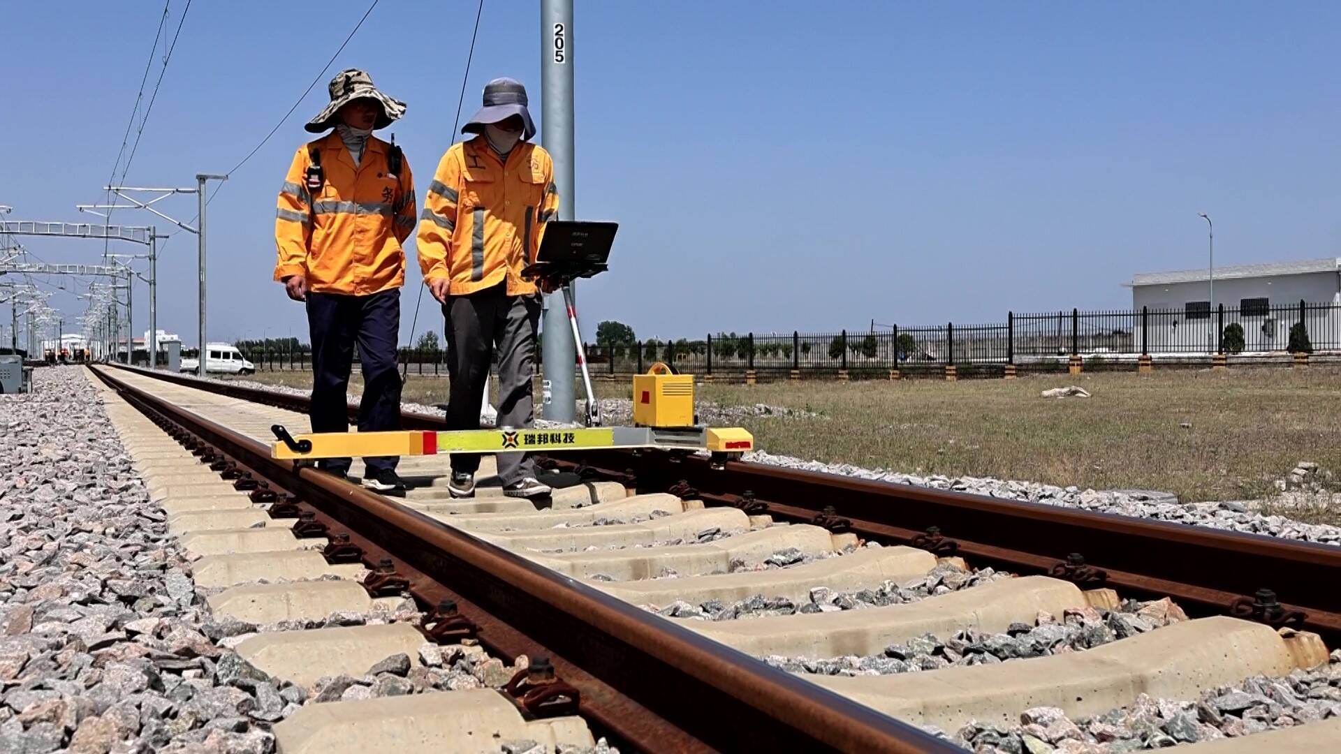
Rail gauge is the single number most often quoted about a track, and the one most often quoted carelessly. A gauge reading taken at the wrong height on the rail head, with an uncalibrated tool, or without the cross level and alignment values that belong beside it, can send a maintenance crew to the wrong location. This guide sets out what rail gauge actually measures, how the tool hierarchy from a mechanical ruler to a recording trolley differs in accuracy and what each class is permitted to certify, the tolerance bands and inspection frequencies that apply, and the errors that produce readings nobody can act on. It is written for track engineers, permanent way supervisors and procurement teams specifying measuring equipment. In one sentence: rail gauge is the minimum distance between the working edges of the two rails measured within 16 mm of the top of the rail head, and it only means something when read together with cross level, alignment and rail wear at the same location. Rail gauge is defined as the minimum distance between the working edges — the gauge faces — of the two rails, measured within a band 16 mm below the top of the rail head. That definition comes from the Chinese Technical Regulations for Railway Traffic, and the 16 mm figure is not arbitrary: because the rail head is a curved profile and the wheel flange is also curved, the point where the flange actually contacts the rail normally falls between 10 mm and 16 mm below the running surface. Measuring at the contact zone rather than at the surface means the number reflects the geometry the wheel actually experiences. The implications of that definition are worth stating plainly, because most field disputes about gauge come down to them: Standard gauge is 1435 mm, fixed as the international standard in 1937 and now used by roughly 60% of the world's route length. The story of how that figure came to dominate — and what it means for maintenance practice on a network built to it — is treated separately in our article on why 1435 mm gauge became the world standard. What matters here is that networks are not all built to it. Broad gauge includes 1520 mm in Russia and Finland, 1524 mm on some legacy alignment, and 1676 mm in India, Pakistan, Argentina, Chile, Spain and Portugal. Narrow gauge includes 1067 mm in Japan's conventional network and in Taiwan, China, and 1000 mm metre gauge in parts of Africa and Southeast Asia. In China, standard gauge dominates, with 1067 mm in Taiwan, China and a 1000 mm narrow-gauge section on the Kunming–Hekou route. Gauge affects the tooling as well as the track — grinding wheels for 1520 mm gauge are a separate specification problem from standard-gauge wheels. In practice the measuring tool does not hunt for the 16 mm plane. A mechanical or digital gauge has two contact pads that rest on the rail heads; the geometry of the tool places the measuring faces in the correct plane automatically, provided the tool is seated properly and the pads are not sitting on a burr, a weld collar or accumulated debris. Two consequences follow. First, a tool that is not properly seated reads short or long by an amount nobody can see in the display. Second, on a rail with significant gauge face wear or side wear, the 16 mm window may sit in a region where the face is no longer vertical — the worn face curves away — and the "minimum distance" is then found slightly differently depending on the tool and the measurement system. This is the reason a recording trolley and a hand gauge can disagree on the same section, and it is covered in more detail below. Why measure it at all? Because gauge is the geometric parameter with the most direct relationship to derailment risk. A wide gauge allows the wheel flange to drop between the rails; a tight gauge squeezes the wheelset and forces flange contact on both sides at once. Neither needs to reach an extreme value to be dangerous: a short length of rapid gauge change — a gauge variation spike — is enough to unload a wheel and trigger a derailment at speed. That is why the regulations manage gauge not only by absolute value but by rate of change along the track. Track gauges are a hierarchy, not a single product. Each level trades accuracy for coverage, and the choice is governed by the acceptance standard the operator has to demonstrate. The classic track gauge — known in Chinese practice as the dao chi, or track rule — is a rigid bar with two contact pads and a graduated scale. The governing standard is TB/T 1924—2008, Standard Gauge Railway Track Gauge, which covers both mechanical and electronic types and sets the performance floor for the category. For a mechanical gauge the standard specifies a measuring range of 1420 mm to 1460 mm, a minimum scale division of 1 mm, a permissible indication error of ±1 mm, and a controlled measuring force of 50 N ± 10 N. Indication stability — the spread across ten consecutive measurements — must not exceed 1 mm, repeatability across 30 consecutive measurements must stay within 1.5 mm, and calibration is carried out at a controlled 20 °C ± 5 °C. The controlled measuring force is one of the most commonly ignored requirements in the field. A gauge pressed hard against the rails reads differently from one resting under its own spring load, and the ±10 N band exists precisely because that difference is measurable. The electronic gauge — digital track gauge or digital display gauge — replaces the spirit level and the engraved scale with displacement and angle sensors, an embedded processor and an OLED display, with temperature compensation built in to remove the effect of thermal expansion on the bar itself. Range and environmental specification improve as well: rail gauge measuring range 1410 mm to 1470 mm, superelevation and cross level range −185 mm to +185 mm, operating temperature −30 °C to +55 °C, bar length 1600 mm and unit weight around 2.8 kg. The decisive difference is accuracy class. Digital gauges are graded 0, 1 and 2, and the grades map directly onto permitted line speed: Turnout work adds two more quantities to the same instrument: check gauge (1381 mm to 1401 mm) and back-to-back flange clearance (1338 mm to 1358 mm), both typically specified to ±0.30 mm, because a turnout is where wheel geometry and rail geometry interact most tightly. Two operational facts deserve attention. First, a hand gauge cannot verify a high-speed line. At 300 km/h the acceptance standard for gauge is around ±1 mm; a mechanical gauge with a ±1 mm permissible error and a 1 mm scale division has a measurement uncertainty the same size as the tolerance it is being asked to police. The certificate is not worth the paper. Only a class 0 instrument has the resolution to support that decision. Second, digital gauges must be calibrated periodically — the conventional interval is no more than three months, because the pads wear and the sensors drift — and the gain from switching from manual to digital measurement in field studies has been reported as roughly 40% faster in tangent track and around 60% faster in curves, largely because there is nothing to read off by eye. Above the hand gauge sit recording instruments that capture the whole geometry vector continuously rather than one parameter at one point: RailwayCare supplies this class of equipment for field and trolley-based operation, from digital gauges through to track and rail inspection equipment covering geometry parameters and rail condition in the same product family. Reading that table in a procurement context is straightforward: buy to the acceptance standard, not to the price. A class 2 gauge is the correct instrument for a low-speed yard and the wrong one for a high-speed handover, and no amount of careful operating practice closes a resolution gap. Chinese permanent way practice manages static track geometry through the permissible deviation values in TG/GW 102—2019, the Rules for Maintenance of Conventional Speed Railway Lines. The values are graded by permitted line speed and by management level — work acceptance, scheduled maintenance, and emergency repair — which means there is no single "permitted gauge deviation" for a network. There are several, and the applicable one depends on what the measurement is for. For concrete sleeper track, the gauge deviation values are: Three footnotes govern how those numbers are used, and each of them is a common source of argument: Two further requirements sit outside the table. Gauge variation must be smooth rather than abrupt: the rate of change is limited to 2 mm/m on main and receiving track, 1 mm/m where permitted speed exceeds 120 km/h, and 3 mm/m on other siding track. And in curves, deliberate gauge widening is applied by radius — approximately 1450 mm below 300 m radius, 1440 mm for 300–350 m, and standard 1435 mm above 350 m — which is why a curve can read "wide" and still be entirely correct. Turnouts carry their own values, and one of them is stricter than anything in the table above: at the switch rail tip, the work acceptance tolerance is ±1 mm. Turnout check gauge is measured against a separate table, and on diverging curves the limit for the outer rail being lower than the inner rail is zero at work acceptance, 2 mm at scheduled maintenance and 3 mm at emergency repair. Inspection frequency follows the same logic of matching effort to consequence. Static inspection of main line track and turnouts is normally carried out twice a month, reduced by one where a recording car has covered the section, while other lines and turnouts are inspected once a month; gauge, cross level and twist are recorded in full at every such inspection. Curve versines are surveyed comprehensively at least once a quarter, and the check on welding joint surface quality and straightness is a six-monthly item. Dynamic inspection is scheduled by traffic. Recording cars cover lines above 120 km/h at least twice a month; on main line where annual gross tonnage reaches 80 million tonnes, the interval tightens to 15–30 days; between 25 and 80 million tonnes it is monthly; below 25 million tonnes, quarterly. On high-speed lines, comprehensive static geometry coverage is normally required at least monthly, with additional surveys immediately after tamping, after stress release on continuously welded rail, and after flood reinstatement. Gauge does not drift for one reason. It drifts for several at once, and identifying which is present is the whole diagnostic task. A useful discipline is to group the causes by whether they displace the rails laterally or change the effective position of the gauge face. Causes of gauge widening: Causes of tight gauge: That last case deserves its own explanation, because it produces a specific and well-documented conflict between measurement methods. In corrective lining work, the gauge is set so that the distance between the rails at 16 mm below the head measures 1435 mm. On a side-worn rail, however, the geometry changes rapidly below that plane: the worn face slopes away, so the gauge at 25 mm or 30 mm below the head is appreciably smaller than at 16 mm. A recording car using an optical or non-contact head can register its measuring point slightly lower than the 16 mm plane on a worn section, and the section then reports tight gauge that the hand gauge does not see. Both instruments are working correctly; they are measuring different geometry on a rail that is no longer the profile it was designed to be. The practical resolution is to read the gauge record together with the wear measurement, which is precisely why the two are collected in the same survey. There is one more cause that produces numbers with no physical basis at all: false gauge. Where a gauge bar, rail brace or turnout fitting is not in tight contact with the rail, the gauge face being measured is the fitting rather than the rail. The gauge reads wide because there is a gap behind the brace. Any gauge reading that changes after the fittings are tapped up was never a gauge defect. The same applies where the measuring pads sit on top of a weld collar, a burr or packed debris. Side wear on curves is a maintenance problem in its own right with a developed grinding response, treated in our guide to managing side wear on curved track, and the mechanism by which it develops is set out in the root cause analysis of rail side wear. Gauge measurement and wear measurement are two views of the same deterioration. A gauge value on its own cannot classify a track section. The static geometry vector has four components that must be read at the same location, because they interact: geometry that is acceptable in one component can be made unacceptable by the others. Cross level is the difference in height between the two rails at a single point. On tangent track the tolerance is small — 3 mm at work acceptance on the fastest main line, rising to 5 mm on other siding track. In curves, cross level becomes superelevation, and the measured value is compared against the designed value; the range of measurement on a digital gauge runs from −185 mm to +185 mm for that reason. A cross level error that looks trivial in absolute terms can put the track outside its twist limit when the next measurement point is taken into account, which is exactly the relationship the next section describes. Alignment is the lateral position of the track in plan, and longitudinal level is the vertical profile along the track. Both are measured as a maximum versine on a 10 m chord — 3 mm at work acceptance on the fastest main line, 4 mm in the mid range, 5 mm on siding track — and both are among the quantities a recording trolley captures continuously while a hand instrument can only sample. The reason these belong beside gauge is mechanical. A track with perfect gauge but poor alignment imposes flange contact and lateral loads the gauge value does not predict. In practice, alignment defects and gauge defects share the same root causes — weak sleeper support, uneven ballast support, voiding — and repairing one without the other produces a defect that returns. The relationship between ballast condition and the stability of the track structure is covered in our article on what ballast actually does, and the components that hold the rails to gauge in the first place — rail, sleepers and fastenings — are described in our guide to what railroad tracks are made of. Twist is the change in cross level between two points a defined distance apart, and it is the most safety-relevant of the four because it unloads wheels. It is also the one most often measured inconsistently, because the base length is not the same for every instrument: 3 m with a recording trolley, 6.25 m with a hand gauge. A crew comparing its own twist value against a recording car's exception list without checking the base length will spend a shift chasing a discrepancy that does not exist. The requirement that no twist above the tabulated value appears within any 18 m length exists because a single point measurement cannot see a twist that develops across several measurement positions. This is a general principle worth applying to all four components: a compliant set of point readings can still describe a non-compliant track. Because gauge is measured within 16 mm of the rail head top, and because both side wear and vertical wear act within that region, the gauge record cannot be interpreted without the wear record. The two are measured in the same survey for a reason. Wear is normally quantified as vertical wear at the head centre and lateral wear at the gauge face, with limits set by rail section and by permitted speed; the measurement practice, the instruments and the decision rules for grinding versus replacement are set out in our guide to rail wear measurement. Three interactions matter when the two records are read together: Gauge and profile are also linked through the acceptance criteria for the finished surface. The Chinese permanent way rules limit gauge defect to values measured with a ruler and depth gauge, and the treatment limits for rail defects generally are set out in our review of rail defect types and treatment. Where a defect exceeds the treatable limit — including gauge-related head defects beyond roughly 1 mm at 200–250 km/h and 0.8 mm at 250–350 km/h — the rail is replaced rather than dressed. The errors below account for the majority of gauge records that cannot be acted on. None of them requires a defective instrument; they arise from how the measurement is taken and what is recorded with it. A gauge measurement that is not recorded in a form that supports comparison has limited value. The record that supports both handover and trend analysis contains, for each measurement location: The classification is what turns a record into a work order. Emergency repair exceptions are normally handled within a defined short window, scheduled maintenance exceptions are programmed into the forward plan, and work acceptance exceptions feed the next maintenance cycle. Records that skip the classification step tend to be re-measured rather than repaired. For a programme that has to demonstrate conformance after grinding or tamping, the same data set is what proves the work: the pre-work survey sets the scope, the post-work survey is the evidence. Where the geometry defect is a profile defect rather than a position defect, the verification method changes and the process for removing corrugation and verifying the result sets out how the result is demonstrated on the finished surface. Where the work is at a turnout, geometry, wear and profile all have to be verified in a confined space, which is the subject of our guide to turnout grinding and inspection practice. RailwayCare supplies portable, field-ready inspection equipment for the two tasks a permanent way crew performs on every patrol: measuring track geometry parameters — gauge, cross level, alignment and longitudinal level — and assessing rail condition, including profile wear and internal flaws. All instruments are designed for manual or trolley-based operation, which is what makes them suitable for crews working inside short possessions and for the routine surveys that inspection schedules are built on. The range maps onto the hierarchy described above: If you are specifying gauges for a network, the two questions that determine the answer are the permitted speed of the lines to be surveyed and whether the measurements will be used for acceptance or for trend monitoring only. Send us the speed bands, the track types — tangent, curve, turnout, yard — and the form in which the records have to be submitted, and we will recommend the instrument class for each duty rather than a single compromise. Our wider scope for permanent way work, including rail maintenance equipment for lifting, lining, tamping and rail replacement, is set out in our rail maintenance solution overview, and the inspection side of the programme in our rail inspection solution pages. WhatsApp: +86 15072332788 Email: simon.wang@railwaycare.com With a track gauge — a bar instrument with two contact pads that seat on the rail heads and place the measuring faces in the 16 mm plane below the top of the head. The gauge is read at the point of measurement, or stored automatically in a digital instrument. For continuous recording, a track geometry trolley runs along the rail heads at 2–4 km/h and captures gauge together with cross level, longitudinal level, alignment and twist. The measuring principle is the same in every case: the minimum distance between the two working edges within the 16 mm band. A comparison of the instrument classes and what each is permitted to certify is set out in this answer on track geometry measurement. There are four common reasons, and they are distinguishable. Fittings may have loosened or been tapped up between visits, which changes what the gauge is actually measuring. A different instrument class may have been used, with a different resolution and a different measurement plane on a worn rail. The section may genuinely have moved, from lateral loading, sleeper movement or voiding. Or the readings may have been taken at different points along the track rather than at a marked location. Recording position to a stable reference — and noting the instrument and its calibration date — removes the ambiguity. Where a hand gauge and a recording system disagree specifically on a side-worn curve, the wear measurement usually explains why; the instruments that carry out that measurement are listed among the railway track maintenance machines used for geometry work. There is no single figure. Under the Chinese permanent way rules the permissible gauge deviation is graded by permitted line speed and by the purpose of the measurement — work acceptance, scheduled maintenance or emergency repair — and the same section can therefore be within tolerance for one purpose and outside it for another. On concrete sleeper track, work acceptance ranges from +2/−2 mm on the fastest main line to +6/−2 mm on siding track, with emergency repair values at +6/−4 mm and +19/−9 mm respectively. Independently of any deviation value, total gauge including curve widening must never exceed 1456 mm. Speed restrictions follow the emergency repair and limit columns rather than the deviation values alone. The wider framework of infrastructure inspection that these values sit inside is described in this overview of rail infrastructure inspection. Not ideally, and the reason is specification rather than convenience. Turnout measurement adds check gauge and back-to-back flange clearance, both specified to around ±0.30 mm, and the switch rail tip carries a work acceptance tolerance of ±1 mm — tighter than anything applied on plain line. A general-purpose gauge that covers the main line geometry may or may not carry the turnout parameters, and a class 2 instrument will not have the resolution to support that ±1 mm figure. The practical answer is to specify against the tightest duty the crew will actually perform. The wear side of turnout inspection is a separate instrument again, because frog wear is measured against a depth reference rather than between the rails. By two schedules that run in parallel. Static inspection of main line track and turnouts normally happens twice a month, reduced by one where a recording car has covered the section, and once a month on other lines; gauge, cross level and twist are recorded in full at each inspection, curve versines are surveyed comprehensively at least quarterly, and welding joint surface quality is checked six-monthly. Dynamic inspection runs on traffic: recording cars cover lines above 120 km/h at least twice a month, tightening to 15–30 days where annual gross tonnage reaches 80 million tonnes and relaxing to quarterly below 25 million tonnes. High-speed static coverage is normally monthly, with additional surveys after tamping, stress release or flood reinstatement. The logic these schedules rest on — that intervals are set by how fast the defect condition develops rather than by a fixed calendar — is the same principle that governs grinding intervals for rail surface condition. One whose permissible error is small compared with the tolerance being verified. On a line where the gauge acceptance standard is around ±1 mm, a mechanical gauge with a ±1 mm permissible error and a 1 mm scale division has the same uncertainty as the tolerance it is policing — the measurement cannot support the decision. A class 0 digital gauge, with ±0.25 mm permissible error and 0.01 mm resolution, is the appropriate hand instrument, and for handover surveys a recording trolley calibrated to ±0.5 mm on gauge produces the trace the acceptance record needs. Beyond instrument class, the non-negotiables are current calibration, correct seating of the pads, and recording the wear values from the same location so that the gauge figure can be read against the rail that actually exists.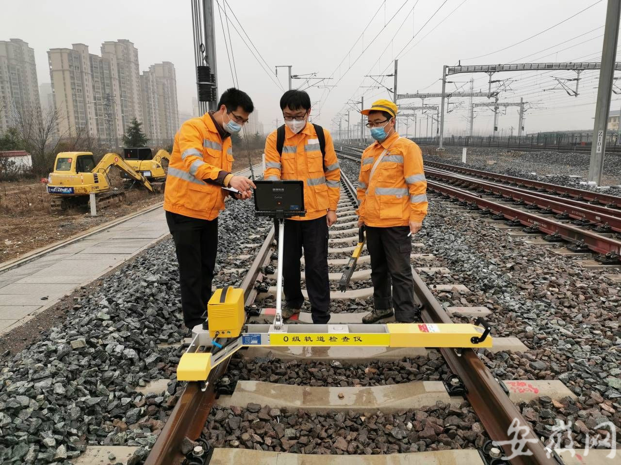
What Rail Gauge Means and Why It Is Measured
Where the Measurement Is Taken, and Why That Position Matters
Railroad Track Gauge Tools: From Simple Gauges to Measuring Systems
Mechanical Track Gauges
Digital Track Gauges and Their Accuracy Classes
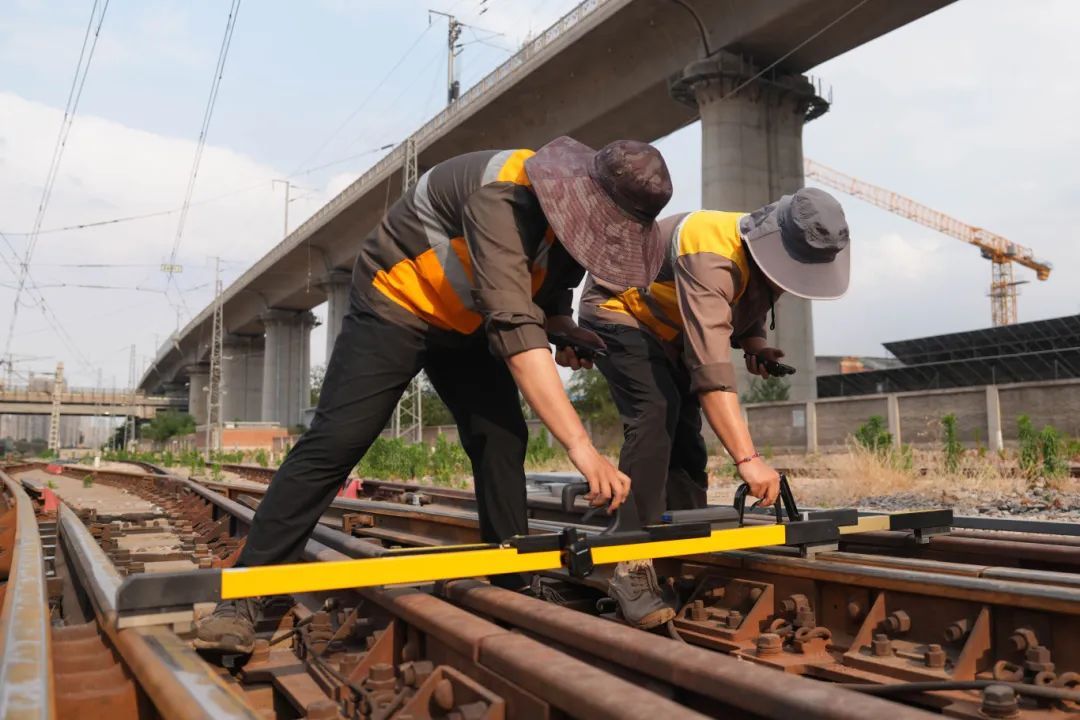
Track Geometry Measurement Systems and Recording Trolleys
Level Typical instrument Accuracy on gauge Output Where it applies 1 Mechanical track gauge ±1 mm, 1 mm division Single reading, point by point Tangents, yards, slow-speed lines, spot checks 2 Digital gauge, class 2 / 1 / 0 ±0.30 / ±0.25 / ±0.25 mm Single reading, stored and timestamped Class 0 required for high-speed acceptance 3 Recording trolley Calibrated to ±0.5 mm Continuous trace of gauge, cross level, level, alignment, twist Full-section static survey and handover records 4 Track recording car / GNSS-INS system Line-speed indirect measurement Quality indices, exception lists, trend data Network monitoring, maintenance planning, verification Rail Gauge Standards: Tolerances and Inspection Frequencies
Permitted speed Work acceptance Scheduled maintenance Emergency repair Above 160 km/h +2 / −2 mm +4 / −3 mm +6 / −4 mm 120–160 km/h +4 / −2 mm +6 / −4 mm +8 / −6 mm 80–120 km/h +6 / −2 mm +7 / −4 mm +14 / −7 mm ≤80 km/h main and receiving track +6 / −2 mm +7 / −4 mm +16 / −8 mm Other siding track +6 / −2 mm +9 / −4 mm +19 / −9 mm Gauge Widening, Tight Gauge and Their Causes
Reading Gauge Together with Cross Level, Alignment and Twist
Cross Level and Superelevation
Alignment and Longitudinal Level
Twist and the Base Length Question
Measuring Rail Wear and Profile Alongside Gauge
Common Measurement Errors and How to Avoid Them
What Should Be Recorded After a Gauge Check
Buy Track Gauges and Measuring Tools from RailwayCare
How is rail gauge measured on track?
Why does the same section read differently on different days?
What tolerance is acceptable before a speed restriction applies?
Can one gauge tool cover both mainline and turnout work?
How often should track geometry be checked?
Which measuring tool suits a high-speed line?